
Comparison of appearance, functional, ergonomic, assembly, and environmental membrane switch prototype samples

Overview

What Is a Membrane Switch Prototype?

Direct definition: A membrane switch prototype is an early functional or appearance sample of a layered control interface. It helps a project team evaluate how the switch fits the product, how keys feel, how graphics appear, how the circuit connects, and whether the design should move toward production.

A prototype is not one universal type of sample. Some projects first need to check graphics and enclosure fit. Others need key function, tail routing, connector alignment, lighting, or user feedback. The right prototype scope follows the actual decision the team needs to make.

It should also be treated as a controlled revision. A sample can reveal practical issues, but it does not by itself guarantee final production performance. Final construction, tooling, materials, process conditions, and acceptance criteria must be confirmed before production release.

Prototype TypeMain PurposeTypical Questions
Appearance prototypeReview graphics, dimensions, finish, and product fit.Does the panel match the enclosure and approved artwork?
Functional prototypeReview circuit operation, key actuation, and connector interface.Do all keys and circuits work as intended?
Ergonomic prototypeReview key position, tactile response, and user interaction.Can users operate the interface comfortably and accurately?
Assembly prototypeReview installation, tail routing, adhesive, and mechanical alignment.Does the part install correctly in the product?
Environmental evaluation sampleReview defined use conditions.Does the construction address the agreed project conditions?

Decision support

Why Build a Membrane Switch Prototype?

A membrane switch combines visible interface information with a physical and electrical assembly. A prototype gives each stakeholder a common object to review rather than asking people to infer the final result from a drawing alone. It can expose a display-window offset, an awkward key location, an unsuitable tail direction, or an unclear legend before the project reaches a final handoff.

It also helps separate assumptions from confirmed requirements. An enclosure may have a recess, a display, fixing features, or a circuit-board location that changes the construction. Operators may wear gloves, need clear confirmation of a press, or rely on visual feedback. These realities should be reviewed against the actual product.

Prototype decisions it can support

  • Overall size, enclosure fit, and mounting-surface alignment.
  • Graphic overlay colours, legends, display windows, and indicator zones.
  • Tactile or non-tactile feedback, key positions, and user ergonomics.
  • Circuit logic, connector mating, tail exit direction, and routing.
  • Backlighting, LED, rear-adhesive, and project-specific assembly needs.
  • Defined functional and environmental evaluation expectations.
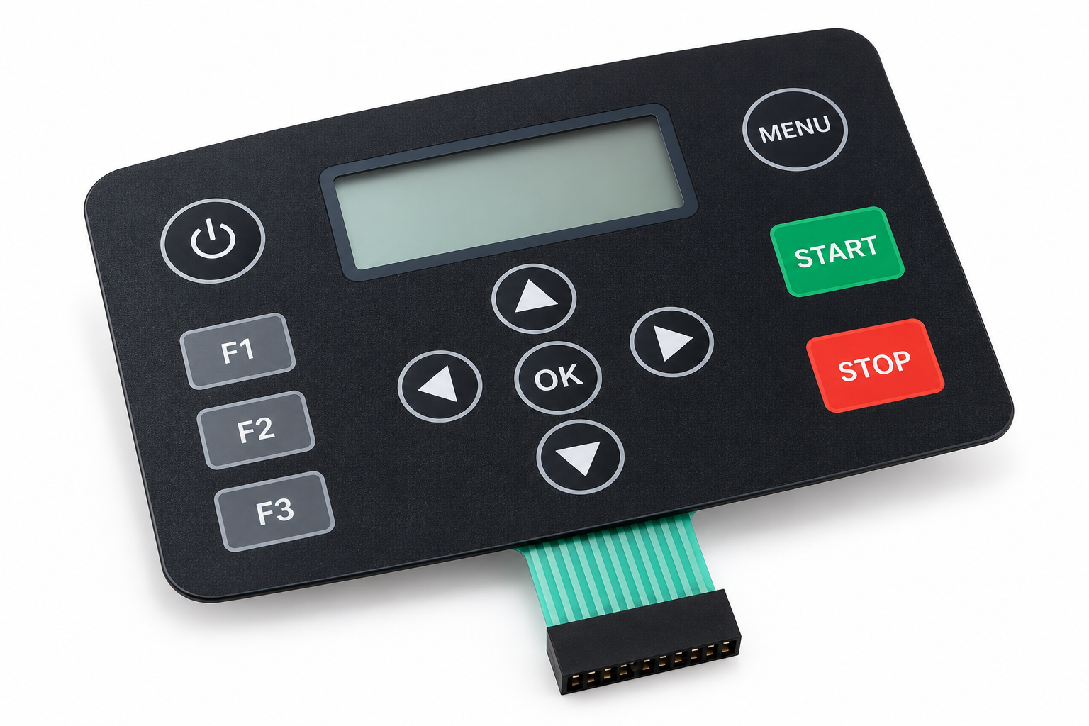
Membrane switch prototype review for enclosure fit, graphic appearance, key layout, and assembly compatibility
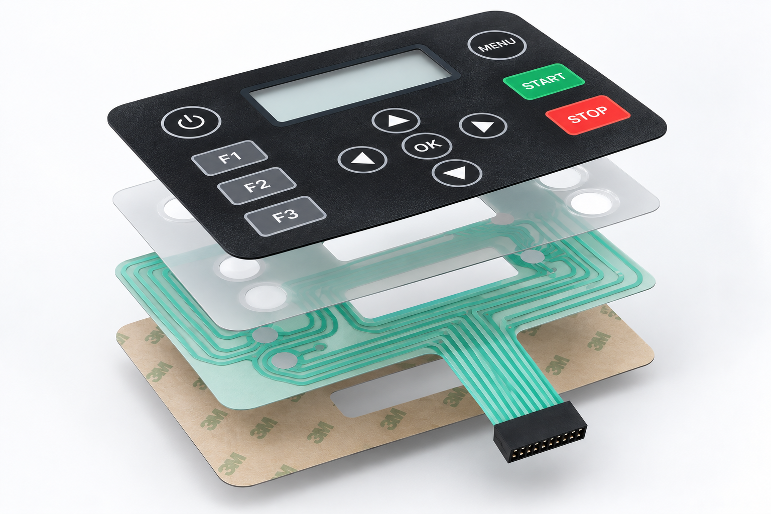
Exploded membrane switch layer stack showing graphic overlay, dome layer, spacer, circuit layers, tail, and rear adhesive

Construction

Review the Layer Stack First

A membrane switch prototype needs a construction direction before meaningful review can begin. The layer stack connects the visible overlay, intended key response, circuit arrangement, tail, adhesive, and any reinforcement or lighting needs. It should reflect the real application instead of a generic drawing.

Not every membrane switch includes every layer listed below. The final layer stack should be defined for the project. For example, dome structures, support layers, lighting features, and adhesive areas depend on the approved design and installation conditions.

LayerTypical FunctionPrototype Review Question
Graphic overlayVisible user interface with legends, icons, and windows.Are colours, text, symbols, and windows correct?
Graphic adhesiveBonds overlay to underlying layers where applicable.Is the construction aligned and suitable for the design?
Dome retainer or dome layerHolds tactile domes in place when used.Are dome positions and key centres correct?
Spacer layerCreates separation between circuit contacts.Are key openings and spacing correct?
Upper and lower circuit layersCarry conductive paths in selected constructions.Does the circuit layout align with the key design?
Rear adhesiveBonds the final assembly to the enclosure or backer.Is the adhesive area compatible with installation?
Backer or reinforcementAdds support where required.Is rigidity or support needed for the product assembly?

User interaction

Choose Tactile or Non-Tactile Keys

Tactile designs provide a physical response when a key is pressed. Non-tactile designs do not provide a snap response and may rely on visual, audible, or system feedback. Embossing can help a user locate a key, but it is not automatically the same as electrical tactile feedback.

The best choice depends on the application. A control panel used with gloves, in a noisy environment, or where a user needs confident confirmation may be reviewed differently from a panel that has a display, sound, or other system feedback. A physical membrane keypad prototype gives the team a practical way to compare the interaction.

Questions for Tactile Feedback Review

  • Is physical click feedback required?
  • Will the operator wear gloves?
  • Is the product used in a noisy, dark, wet, or vibrating environment?
  • Are repeated presses expected or is accidental activation a concern?
  • Is embossing required to locate keys by touch?
  • Is visual or audible system feedback available?
  • What user feedback should be collected from the prototype?
Tactile metal dome membrane switch beside a flat non-tactile membrane switch panel
FeatureTactile Membrane SwitchNon-Tactile Membrane Switch
User feedbackPhysical snap or response from the key structure.Usually relies on visual, audible, or system feedback.
Common structureMay use metal domes or formed polyester domes.May use flat or lightly embossed key zones.
Prototype focusFeel, actuation consistency, and key position.Clear graphics, prevention of unintended input, and system feedback.
User environmentConsider gloves, repeated use, fatigue, and required confirmation.Consider display feedback, sound, lighting, and operator training.
Design decisionRequires agreed tactile target and key arrangement.Requires agreed non-tactile feedback method.
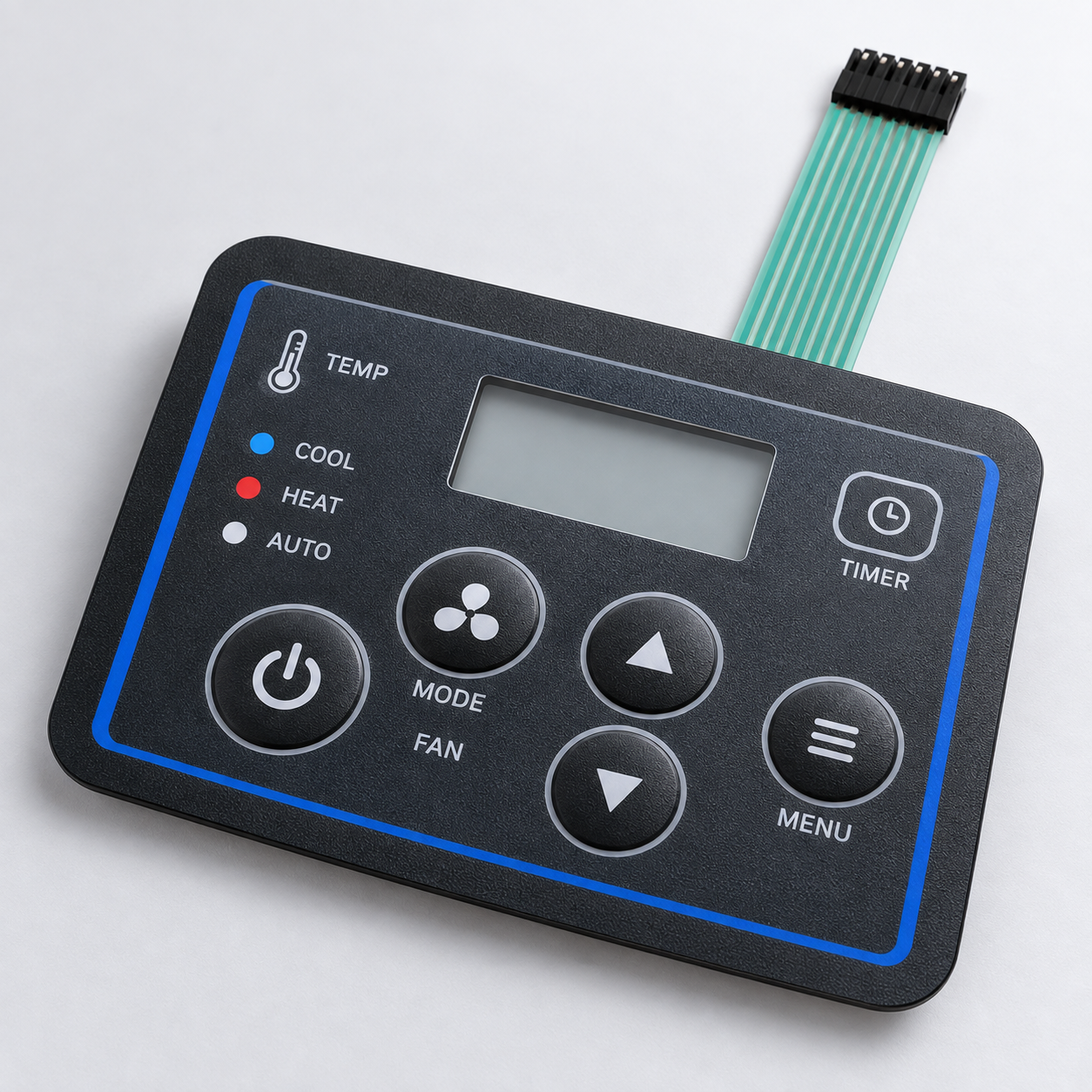
Membrane switch graphic overlay prototype with icons, embossed keys, display window, and indicator areas

Visible interface

Prepare the Graphic Overlay

The graphic overlay is the visible interface. It should be reviewed for readable text, key identification, display alignment, indicator visibility, approved colour direction, surface-finish needs, and user navigation. A graphic overlay prototype makes it easier to check the relationship between the printed interface and the enclosure beneath it.

Keep artwork revision control simple and visible. Product names, logos, icons, legends, warning information, and display-window positions should refer to the same approved revision as the mechanical and circuit information. This reduces the risk of approving a visually correct panel with outdated key names or window locations.

Graphic ElementPrototype Review Question
Text and legendsAre labels readable at normal operating distance?
Icons and symbolsAre functions understood without ambiguity?
Display windowIs alignment correct with the display beneath it?
ColourDoes the sample match the approved colour direction?
TextureDoes the selected finish support the product use case?
EmbossingDoes it help key location and user interaction?
Transparent areaDoes it show the intended indicator or display clearly?
Warning informationIs required information present and readable?

Electrical integration

Define the Circuit and Connector Interface

A custom membrane switch prototype should confirm both user-interface design and electrical integration. A clean visual sample is not enough if the key map, circuit logic, pinout, tail route, or connector orientation cannot be checked against the target board and enclosure.

Share the latest schematic, connector drawing, and PCB reference whenever they are available. The project team should agree who validates key mapping, pin numbering, ground or LED connections where applicable, and the mating orientation. This helps turn a membrane switch sample into a useful integration review.

Prototype circuit checklist

  • Confirm connector mating orientation and pin numbering.
  • Confirm the tail does not interfere with enclosure features.
  • Review bend direction, clearance, and strain considerations.
  • Check key mapping against the approved circuit logic.
  • Test every intended key function.
  • Review LED or backlight circuits separately if used.
  • Confirm the prototype matches the latest schematic revision.
Membrane switch circuit tail with pinout labels connected to a printed circuit board
RequirementWhat to Define
Key logicWhich keys connect and what action each key performs.
Circuit typeSingle circuit, matrix, common bus, or another approved arrangement.
PinoutPin number, key function, ground, LED, shield, or other connection requirements.
Tail exitTail location, direction, length, bend area, and strain considerations.
TerminationBare contacts, connector housing, solder tabs, or another interface requirement.
ConnectorPitch, orientation, mating part, and PCB location.
Drawing referencesSchematic, connector drawing, pinout table, and PCB orientation.
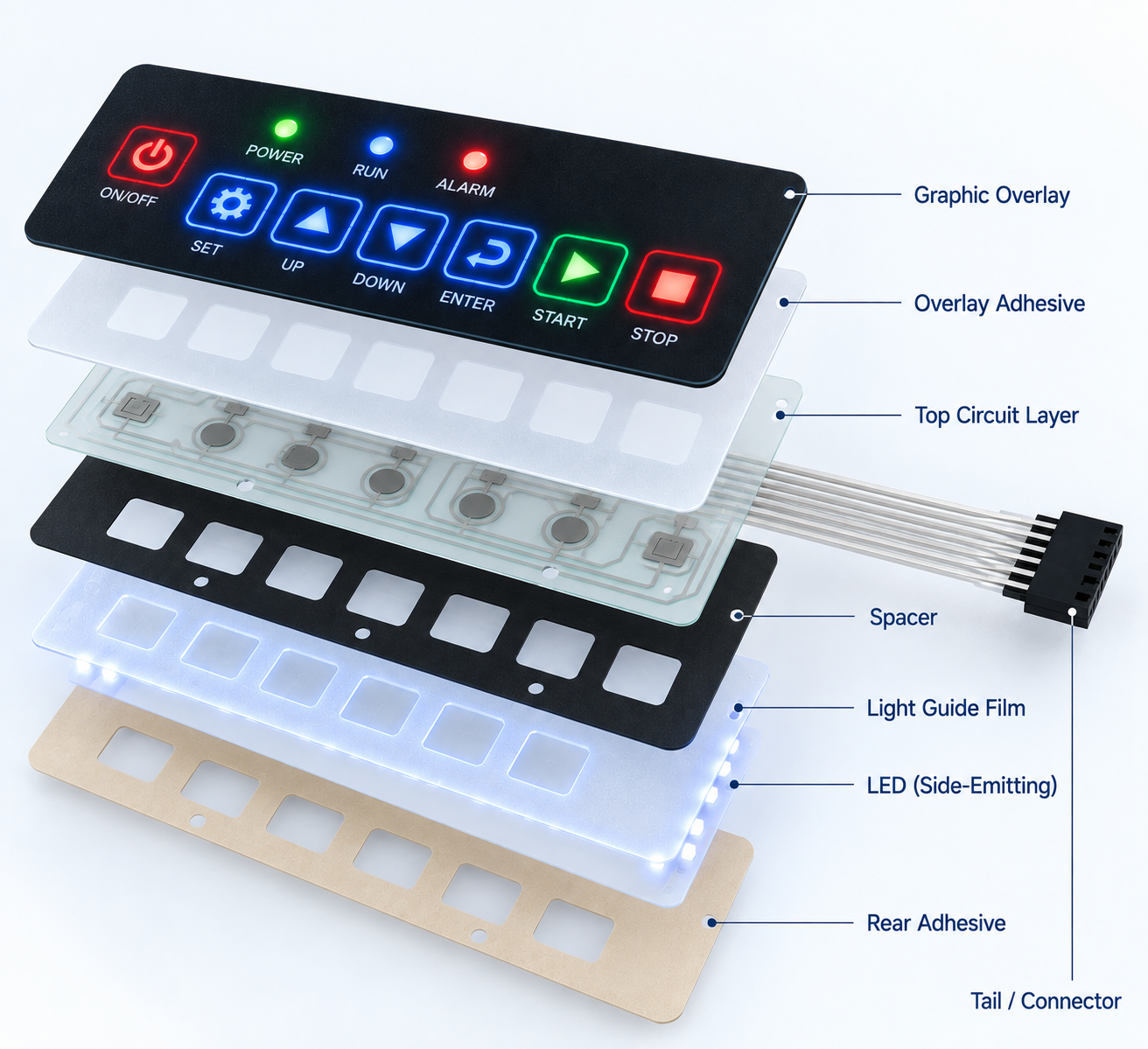
Membrane switch prototype with LED backlighting, light guide layer, and illuminated key icons

Lighting direction

Plan Backlighting Early

Backlighting can affect the layer stack, circuit design, power requirements, key appearance, display windows, available assembly space, and prototype testing. It should be identified early enough for the team to review the intended visual result and electrical interface together.

No lighting method should be assumed. LED backlighting, light guide film, electroluminescent lighting, or indicator windows each need project-specific confirmation. The selected solution must be confirmed for the application, available space, circuit, connector, visibility expectations, and agreed review plan.

Lighting DirectionPrototype Review Focus
No backlightingVerify daylight readability and icon contrast.
LED backlightingConfirm LED positions, light distribution, power, and connector requirements.
Light guide filmReview evenness, key illumination, and assembly space.
Electroluminescent lightingConfirm brightness, power needs, and expected operating conditions.
Indicator windowsCheck visibility, alignment, colour, and light-leakage control.

Input package

Prepare Files for a Membrane Switch Prototype

Clear input files reduce uncertainty in membrane switch prototyping and quotation discussions. The aim is not to create unnecessary paperwork; it is to ensure that graphics, mechanical features, circuit information, enclosure constraints, and the purpose of the sample are understood in the same way by the people reviewing them.

If some information is not final, label it clearly. A marked-up sketch can be useful during an early concept stage, but the team should identify what is provisional, what must be tested, and what requires later approval before production release.

Minimum Prototype Brief

  • Product name, application, and overall dimensions.
  • Number of keys, key functions, and tactile or non-tactile requirement.
  • Graphic artwork or a marked-up sketch.
  • Circuit and connector information with tail exit location.
  • Backlighting requirement, if any, plus enclosure or mounting details.
  • Prototype quantity, objective, test plan, and approval criteria.
Membrane switch prototype file package with vector artwork, mechanical drawing, circuit schematic, and pinout table
File or InformationWhat It Should Include
Graphic artworkVector artwork, legends, colours, windows, and visible interface details.
Mechanical drawingOverall dimensions, cutouts, key positions, display windows, and mounting details.
Circuit schematicKey logic, pinout, electrical connections, and relevant component requirements.
PCB referenceConnector location, mating orientation, and interface information.
Layer-stack directionKnown materials, adhesives, domes, backers, and special construction requests.
Enclosure drawing or samplePanel recess, mounting surface, window position, and assembly constraints.
Application briefEnvironment, cleaning, temperature, handling, and user requirements.
Test planRequired methods, acceptance criteria, and approval responsibility.
Engineer testing membrane switch keys, circuit continuity, connector fit, and enclosure alignment

Review and validation

Test a Membrane Switch Prototype

Prototype testing should match the project objective. A visual sample may need a graphics and fit review; a functional sample may need key mapping, connector, and circuit checks. The test plan should be agreed before evaluation so the team knows what is being reviewed and who records the result.

Use the real enclosure, display position, PCB, installation surface, and representative users where practical. A prototype result is most useful when observations are recorded against the controlled sample and drawing revision, rather than remembered after later changes have been made.

Review AreaExample Question
Visual reviewAre graphics, legends, colours, and windows correct?
Dimensional fitDoes the prototype fit the enclosure and display area?
Key operationDoes every key function according to the approved logic?
Tactile feelIs the physical feedback acceptable to target users?
Circuit continuityAre circuit paths and contacts functioning as intended?
Connector fitDoes the tail mate correctly with the target interface?
BacklightingAre illuminated areas visible and aligned where required?
Adhesive installationDoes the prototype install correctly on the intended surface?
DocumentationAre observations recorded against a controlled revision?

Prototype-review process

  1. Confirm the prototype revision and supporting drawings.
  2. Inspect graphics, dimensions, cutouts, and layer alignment.
  3. Test all keys against the approved key map.
  4. Review tactile feel with representative users where applicable.
  5. Confirm tail routing and connector interface in the actual enclosure.
  6. Review lighting or indicator behaviour where applicable.
  7. Evaluate agreed environmental or handling conditions.
  8. Record findings, required revisions, and approval status.

Controlled handoff

Move from Prototype to Production

Production release should follow a controlled approval process. The prototype should help define, but not replace, the final approved production specification. Prototype construction, production tooling, materials, and process conditions may differ and must be confirmed before production release.

Approval records should make changes visible. If the artwork, layer stack, circuit, connector, enclosure, test method, or installation requirement changes after prototype review, the effect on the finished product should be considered before the next revision is released.

Any changes after prototype approval should be reviewed for their effect on graphics, circuit function, fit, tooling, materials, testing, cost, and schedule.
Membrane switch production-release checklist with approved artwork, circuit drawing, sample, and revision documents
Production Release ItemWhy It Matters
Approved artworkPrevents incorrect legends, colours, or product revisions.
Approved mechanical drawingControls size, cutouts, and mounting features.
Approved circuit and pinoutPrevents functional or connector errors.
Confirmed layer stackDefines material, adhesive, dome, and backer requirements.
Approved sample feedbackDocuments prototype changes and decisions.
Test requirementsDefines quality checks and acceptance criteria.
Packaging requirementsDefines protection, labelling, and handling needs.
Revision controlPrevents obsolete files from being used in production.
Membrane switch prototype review showing common issues with tail routing, key alignment, display windows, and artwork versions

Practical prevention

Avoid Common Membrane Switch Prototype Mistakes

Most prototype delays arise because one part of the interface was reviewed in isolation. A key layout can look clear until it is used beside the actual display. A tail can appear correct until it reaches the target PCB. A visual overlay can be approved before the team checks the latest circuit revision.

Use a short, cross-functional review. Bring the enclosure, circuit, graphics, installation information, and evaluation criteria together. The objective is not to make every possibility part of the sample; it is to make the intended decisions explicit.

Common IssueBetter Approach
Starting without an enclosure referenceProvide dimensions, drawings, or a representative sample.
Choosing tactile feel only from a drawingReview physical samples with actual users.
Sending artwork without circuit informationProvide key logic, pinout, tail, and connector details.
Ignoring tail routingConfirm exit direction, length, bend area, and PCB orientation.
Missing display-window alignmentCheck overlay and display placement together.
Assuming a prototype equals final productionConfirm differences in material, tooling, and process before release.
Using unapproved artwork versionsApply clear file naming and revision control.
Testing only appearanceInclude functional, ergonomic, fit, and assembly review.
Ignoring operating conditionsDefine temperature, humidity, cleaning, handling, and exposure requirements.
Leaving acceptance criteria unclearAgree on what constitutes prototype approval before testing.

B2B inquiry guide

How to Request a Membrane Switch Prototype

A useful request gives a supplier enough context to review the project without assuming universal materials, performance, or construction. Be clear about what is known, what needs evaluation, and what the prototype must prove for your team.

  1. Define the application. Describe the product and control-panel function.
  2. Describe users and conditions. State operating environment and user conditions.
  3. Share the enclosure. Provide dimensions, display position, and mounting details.
  4. Define inputs. State number of keys, functions, and required feedback.
  5. Share visible requirements. Provide artwork, symbols, colours, and interface details.
  6. Provide circuit data. Include logic, pinout, tail route, and connector requirements.
  7. Identify special needs. State lighting, shielding, adhesive, or construction needs if known.
  8. Set the review plan. Define objectives, test requirements, approval criteria, and production expectations.
OEM buyer preparing a membrane switch prototype request with drawings, artwork, enclosure sample, and circuit diagram

Information to Include in Your Inquiry

  • Product application, industry, overall dimensions, and mechanical drawing.
  • Enclosure photo, drawing, or sample; key count, key functions, and key map.
  • Tactile, non-tactile, embossing, or dome requirements.
  • Graphic artwork, colour references, icons, legends, display windows, and indicators.
  • Circuit schematic, pinout, tail exit, and connector details.
  • Backlighting or LED requirements, environmental, cleaning, handling, and installation conditions.
  • Prototype quantity, test plan, approval requirements, future production quantity, and target timing if known.
Frequently asked questions about membrane switch prototypes, tactile keys, circuit tails, and graphic overlays

FAQ

Frequently Asked Questions About Membrane Switch Prototypes

It is a sample used to review appearance, fit, user interaction, circuit function, and integration before production. The scope may be visual, functional, ergonomic, assembly-focused, or a combination. Its value comes from testing the controlled sample against the real application, enclosure, circuit interface, and agreed review criteria.

  • Review graphics and key placement.
  • Confirm fit and installation direction.
  • Record findings by revision.

Useful inputs include dimensions, artwork, key functions, tactile preference, circuit logic, pinout, tail exit, connector details, enclosure information, and test objectives. A final package can be developed in stages, but provisional information should be identified clearly so the team understands what the sample is intended to validate.

The decision depends on required user feedback, operating environment, gloves, operator training, system feedback, and product experience. Tactile feedback can give a physical response; non-tactile designs may rely on visual, audible, or system confirmation. A physical prototype can help validate the choice with representative users.

Lighting may be included if the project defines the required lighting method, power, circuit, connector, space, and visibility expectations. Availability and suitability must be confirmed for the specific project. The prototype review should include the agreed illuminated areas, windows, alignment, and intended operating conditions.

Testing should cover the agreed objectives: graphics, fit, key function, tactile feel, connector interface, installation, lighting, and relevant environmental conditions. Use the current drawings and revision identifier, then record observations and required changes. A visual inspection alone does not replace functional or assembly review where those are required.

A graphic overlay is the visible interface layer used for legends, windows, icons, and branding. A membrane switch includes electrical switching functionality. A project may need one or both, depending on the product design. Review the visible overlay and the electrical interface as connected but distinct project requirements.

A prototype is valuable for approval, but final production release should also confirm materials, construction, tooling, drawings, quality requirements, and revision status. Prototype construction and production conditions may differ. Document what the sample confirms and what still requires final production verification.

Contact StikTec with your artwork, dimensions, circuit requirements, connector details, enclosure information, and prototype objectives. Available construction options and project requirements should be confirmed for the specific inquiry.

Finished membrane switch prototype installed on an industrial control panel enclosure

Conclusion

Build a Better Membrane Switch Prototype

A better membrane switch prototype begins with the real application and enclosure, not a generic set of assumptions. Define the layer stack, key feedback, graphic overlay, display windows, circuit interface, tail, connector, and installation direction as one connected project. Then review physical fit and user interaction before production release.

Use an agreed test plan for functional, ergonomic, visual, assembly, and relevant environmental requirements. Keep drawings, artwork, circuit files, sample feedback, and revisions controlled throughout the project. StikTec can discuss buyer-defined requirements for flat / non-tactile membrane switches, embossed / tactile membrane switches, LED backlit membrane switches, graphic overlays, and control panels / product fascias.

Discuss a membrane switch prototype
Membrane switch prototype sample, circuit drawing, and project inquiry form

Project inquiry

Discuss Your Membrane Switch Prototype

Share your membrane switch dimensions, artwork, key functions, circuit requirements, enclosure details, and prototype objectives. StikTec can review the project requirements with you.

Start a conversation

Tell us what you need

Share your application, material requirements or drawing. Our team will route your request to the right specialist.

  • Emailstik@stiktec.com
  • Phone+86 13026625634
  • WhatsAppwa.link/l98mzc