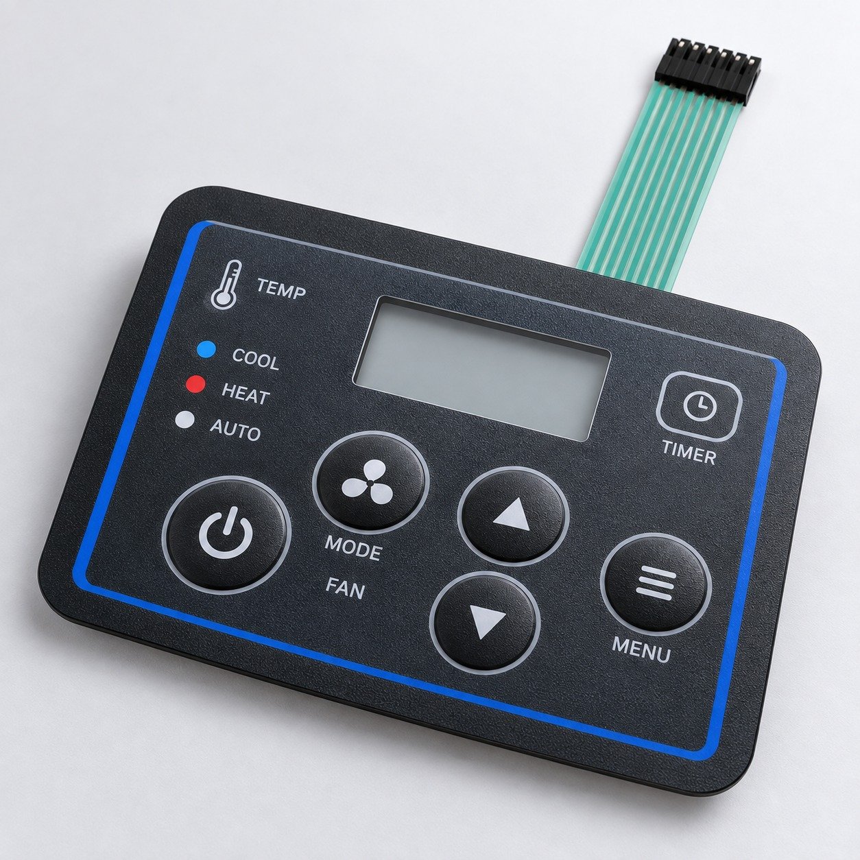
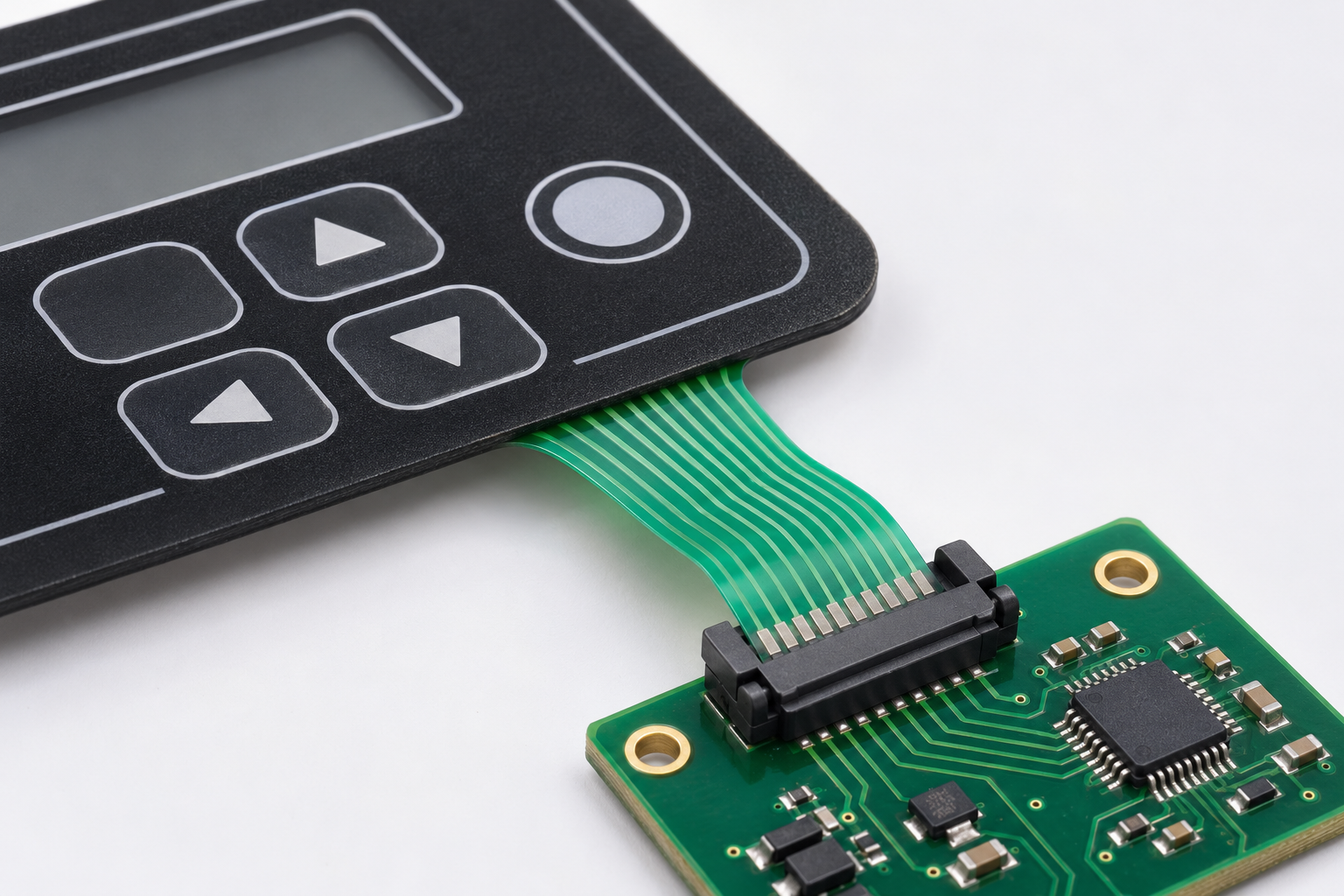
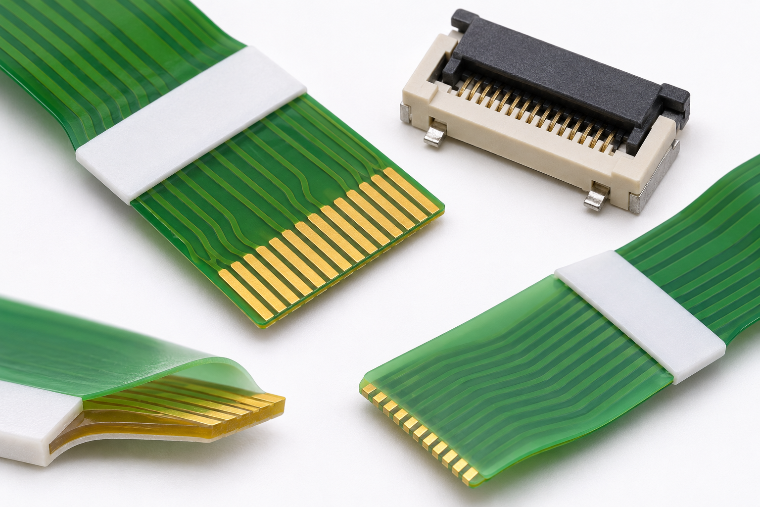
Flexible circuit tail with exposed contact pads, stiffener and matching FFC connector

Overview

What Is a Membrane Switch Connector?

Direct definition: A membrane switch connector is the interface used to join a membrane switch tail to a PCB, cable assembly, or wiring system. The tail carries conductive traces from keys, LEDs, shielding, or other functions. The mating connector, header, or termination establishes the electrical and mechanical connection to the host product.

Membrane switch connector types are therefore a design-interface question. A tail may have printed conductive traces, exposed pads, a stiffened end, a fitted housing, a crimped contact, or another approved termination. The PCB side has its own footprint, orientation, connector mechanism, clearance, and assembly-access requirements.

Compatibility cannot be decided from a name such as ZIF, FFC, FPC, header, or solder alone. It depends on tail construction, contact count, pitch, contact side, tail thickness, stiffener, insertion geometry, PCB connector, enclosure, and the intended assembly method.

Term Meaning
Membrane tail Flexible extension of the switch circuit leading to host electronics.
Termination Prepared tail end or component that makes the electrical interface.
Mating connector PCB, header, or harness-side interface receiving the tail or contacts.
Pitch Center-to-center spacing between adjacent contacts.
Contact side Surface of the tail carrying exposed contact pads.
Stiffener Reinforcement feature used where required by the selected interface.
Pinout Controlled map assigning each contact to a circuit function.

Tail construction

Understand the Membrane Switch Tail

The tail is the flexible circuit extension that carries key signals and any included electrical functions from the active switch area to the host PCB or wiring system. It is not simply a loose cable: its contact layout, exit direction, printing or flex construction, reinforcement, and routing all form part of the approved membrane switch design.

A printed silver membrane tail, an FFC, and an etched copper FPC may require different connector considerations. The suitable interface must be selected from the actual tail drawing and connector documentation. Even apparently similar flat tails may differ in contact-side orientation, thickness, contact finish, insertion length, or support needs.

Tail details to define early

  • Tail construction and conductive system.
  • Contact count, pitch, exposed contact side, and numbering.
  • Exit location, direction, length, routing, and strain considerations.
  • Stiffener position and dimensions if required.
  • Target PCB connector, header, harness, or direct termination process.
  • Enclosure clearance and access for insertion or service.
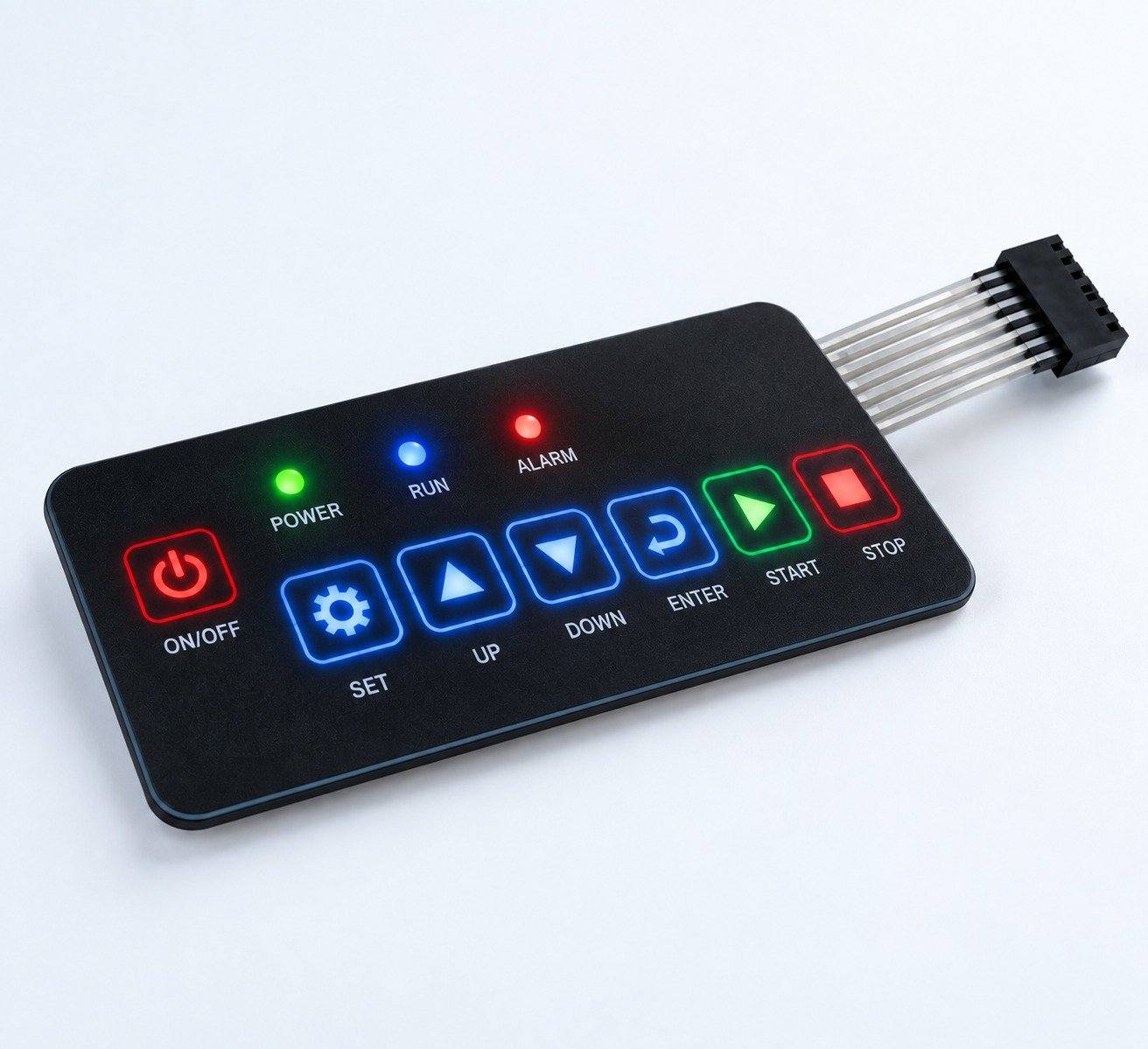
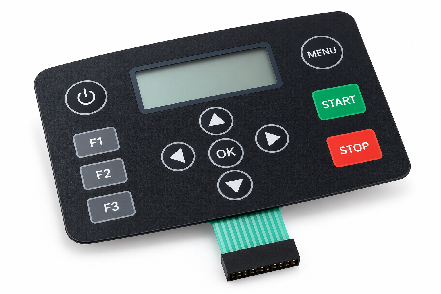
Membrane switch control panel with flexible tail and connector end
Tail Feature Why It Matters
Circuit construction Defines the relevant connection method and interface review.
Contact count Must cover keys, indicators, shields, and other project functions.
Contact side Must face the mating connector contacts as required.
Pitch and pad geometry Must match the selected connector drawing exactly.
Tail thickness and stiffener Can affect insertion and retention compatibility.
Exit and routing Must fit the enclosure and reach the intended PCB location.
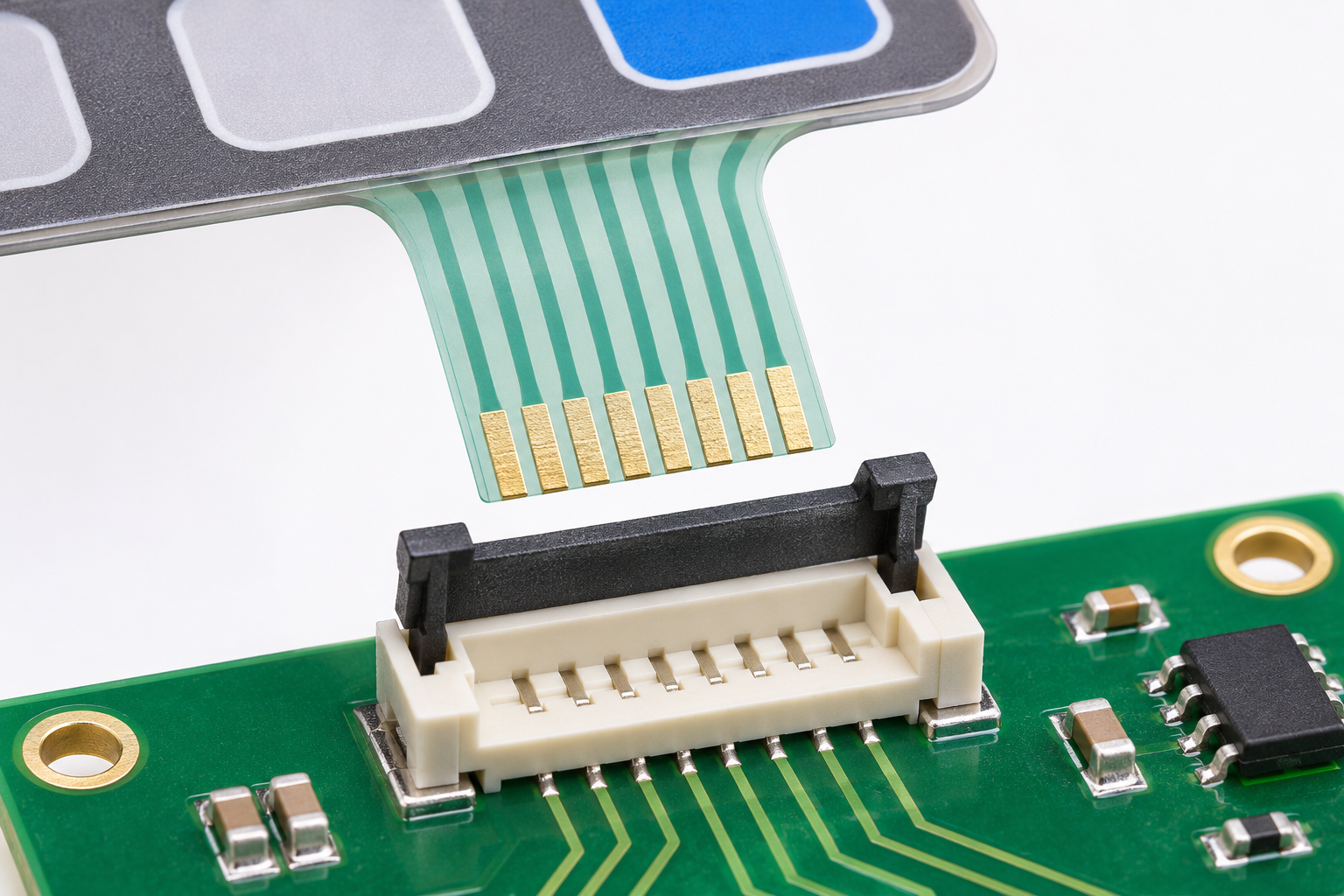
Membrane switch tail aligned above an open PCB-mounted ZIF connector latch

Locking flat-tail interface

ZIF Membrane Switch Connector Options

ZIF commonly describes a zero-insertion-force connector mechanism. A compatible tail is inserted while an actuator or latch is open, then the latch is closed to secure the contact interface. When the selected tail and connector match, this approach can reduce insertion stress compared with forcing a flat tail into a contact system.

ZIF is a connector-actuation method, not a complete compatibility specification. Tail pitch, contact side, thickness, stiffener, insertion geometry, contact length, connector footprint, and latch access must also match. The selected connector manufacturer’s current drawing and project engineering review should govern the final decision.

Assembly reminder: Ensure the latch can be reached, opened, and closed after the PCB and enclosure components are in their intended assembly positions.
ZIF Feature Project Consideration
Low-force insertion Can help reduce stress when the matched tail and connector are used.
Locking actuator Requires access for assembly and service.
PCB-mounted interface Requires the correct footprint and orientation.
Tail contact side Must match connector contact direction.
Tail thickness Must match connector acceptance requirements.
Stiffener May be required depending on tail and connector design.
Pitch and insertion depth Must match the approved connector drawing.
ZIF Actuator Style General Consideration
Flip actuator Requires room for the latch to open and close.
Slide actuator Requires linear actuator access.
Other locking styles Must be confirmed against the selected connector drawing.

Friction interface

LIF and Friction-Fit Connector Options

LIF or friction-fit interfaces use insertion force to engage the tail contacts rather than relying on a separate locking actuator. The connector’s contact spring force, retention approach, tail reinforcement, and insertion method become central to the design review.

Do not treat ZIF and LIF as interchangeable terms. One describes a locking, low-force insertion mechanism and the other describes an interface that relies more directly on insertion and contact retention. The selected connector’s current drawing should define the approved tail geometry and assembly method.

LIF review questions

  • Does the tail construction tolerate the intended insertion method?
  • Is the contact side aligned with the connector direction?
  • Is reinforcement needed for the actual connector design?
  • Can the operator access the interface during assembly?
  • Can the tail be serviced without damaging nearby components?
Flexible membrane tails with exposed contact pads and a flat-flex connector interface
Feature ZIF Interface LIF or Friction-Fit Interface
Insertion action Tail is inserted with actuator open, then locked. Tail is pushed into spring contacts.
Locking method Mechanical latch or slider. Contact friction or spring-force retention.
Assembly consideration Requires correct latch operation. Requires controlled insertion and compatible reinforcement.
Tail handling Must match connector and latch geometry. Must tolerate insertion and retention method.
Selection rule Confirm all tail and connector dimensions. Confirm all tail and connector dimensions.
FFC and FPC style flexible tails with gold contacts, stiffeners and a matching connector

Flat-flex terminology

FFC and FPC Connector Interfaces

FFC and FPC are commonly used terms for flat flexible interconnect systems. FFC often refers to flat flexible cable, while FPC generally refers to flexible printed circuit. A membrane switch tail may be discussed alongside these families, but compatibility must still be verified from the specific tail construction and connector drawing.

Printed silver membrane tails and etched copper flex circuits are not automatically interchangeable. Contact material, contact side, pin count, pitch, thickness, stiffener, insertion direction, and locking arrangement need to be controlled. Top-contact and bottom-contact connector orientation can determine whether the exposed tail pads meet the intended contacts.

Interface Detail What to Confirm
Tail construction Printed membrane tail, FFC, or FPC construction.
Contact material Appropriate interface and contact-finish compatibility.
Contact side Top, bottom, or dual-side contact requirement.
Pitch Exact center-to-center spacing.
Pin count Contacts required by circuit and accessories.
Tail thickness Compatibility with connector acceptance range.
Stiffener Position, thickness, and length if required.
Insertion direction Side-entry, top-entry, or other specified geometry.
PCB footprint Must match selected connector part and orientation.

Harness and header interface

Connector Housings and Header Interfaces

A membrane tail may also be terminated with a fitted connector housing or contacts that mate with a compatible header. This can provide a defined mechanical interface when the product uses a board header, intermediate harness, or serviceable connection route.

A housing adds a component and does not remove the need for interface control. Dimensions, pin count, pitch, mating part, polarization, retention, component height, routing, and assembly access must all be confirmed. The enclosure needs room not only for the connected parts, but also for the hand or tool needed to mate them.

Housing and header checklist

  • Identify the exact mating header or wire interface.
  • Confirm pin count, orientation, retention, and polarization needs.
  • Review enclosure height and routing clearance.
  • Define whether a harness is present between panel and PCB.
  • Check access for assembly, inspection, and service.
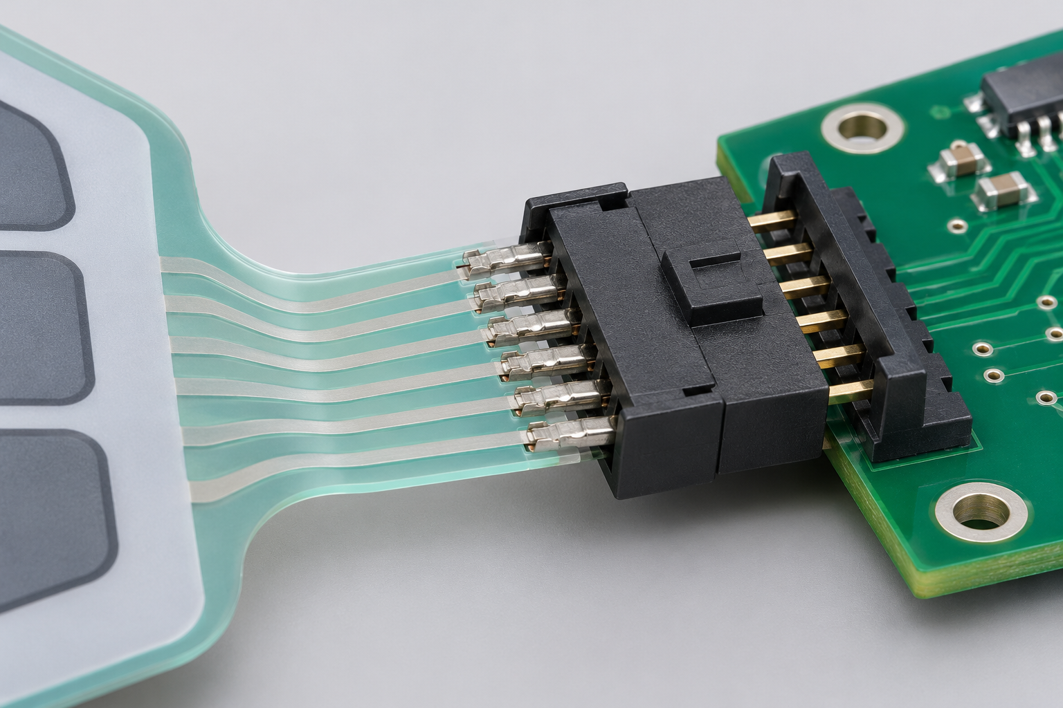
Membrane switch tail with crimp contacts joined to a connector housing and PCB header
Feature Connector Housing or Header Consideration
Housing Provides a defined mechanical interface around contacts.
Header Mating PCB or wire interface with pins or receptacles.
Polarization May help prevent incorrect orientation where included.
Retention May offer positive mechanical connection depending on design.
Height Requires clearance within the enclosure.
Harness use Can be relevant where an intermediate cable is part of the product.
Serviceability May support removal where the design provides for it.
Crimp-contact membrane tail termination joined to a polarized housing and PCB header

Alternative terminations

Crimp, Pin, and Solder Terminations

Some projects use crimped contacts, pins, solder tabs, or direct soldered interfaces. These options must be evaluated for the tail construction, assembly process, heat exposure, mechanical support, stress relief, inspection, and service needs.

Do not select a solder or crimp termination based only on pin count. The selected tail material, conductive system, mechanical support, heat exposure, assembly process, and mating component must be confirmed. A physical prototype may help expose routing and assembly issues, but it does not guarantee final assembly performance.

Termination Type Typical Consideration
Crimped contact May connect the tail to a housing or wire system when compatible.
Pin termination May mate with a corresponding connector or PCB interface.
Solder tab May provide a direct electrical joining point.
Direct solder interface Requires compatible tail construction and controlled process.
IDC or ribbon interface May be considered for selected cable and harness designs.
Heat-seal interface May be used in specialized flat-flex applications where specified.

Interface specification

Specify Pitch, Contact Count, and Pinout

Pitch is the center-to-center spacing between adjacent contacts. It must match the mating connector exactly. Pin count alone is not enough because contacts can be arranged on a different pitch, face the wrong direction, have a different insertion length, or reach a different PCB location.

A controlled pinout links the tail contacts to the switch matrix, LEDs, shielding, and other project functions. It should identify contact numbering, the corresponding PCB connector pins, and the schematic reference. The final mapping must come from approved project documentation, not a generic example.

Illustrative only: A generic pinout table helps explain the format, but the final pinout must be supplied or approved through the project schematic and PCB documentation.
Membrane tail contact pitch aligned to a PCB connector before insertion
Specification Why It Matters
Contact count Must accommodate key circuits, LEDs, shields, and other functions.
Pitch Must match connector footprint and contact geometry.
Pin numbering Prevents key mapping and wiring errors.
Contact side Must align with connector contact direction.
Tail width and contact length Must suit contact layout and insertion design.
Stiffener location May affect insertion and latch engagement.
Connector orientation Must match PCB and enclosure assembly direction.
Tail Contact Example Function
Pin 1 Common line or reference, as defined by project schematic.
Pin 2 Key matrix line or signal.
Pin 3 Key matrix line or signal.
Pin 4 LED, shield, or auxiliary circuit where applicable.
Pin 5 Project-specific function.
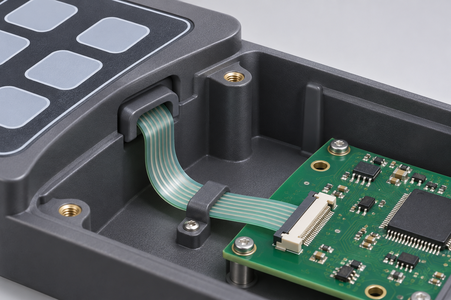
Membrane switch tail routed with clearance through an enclosure to a PCB connector

Mechanical integration

Plan Tail Exit and Routing

Tail exit position, routing, bend direction, and enclosure clearance should be defined during membrane switch design. A correctly matched connector cannot solve a tail that is too short, forced around an obstruction, trapped by a bezel, or inaccessible once the enclosure is closed.

Review the tail route on the final enclosure drawing or a representative sample. Check panel recesses, ribs, fasteners, display modules, moving components, and PCB position. Define a path that allows insertion and locking without tension, sharp folding, twisting, or compression.

Tail Routing Review

  • Verify exit location on the final enclosure drawing.
  • Check keys, LEDs, ribs, fasteners, and display modules.
  • Review bend direction and available clearance.
  • Confirm connector access before enclosure closure.
  • Prevent tension, sharp folding, twisting, or compression.
  • Review service and replacement steps where required.
Tail Routing Factor Prototype Review Question
Edge exit Can the tail leave without interfering with bezel or housing?
Inset exit Is there sufficient support and sealing consideration at the exit?
Tail direction Does it route naturally toward the host PCB connector?
Tail length Can it reach without tension, excess folding, or obstruction?
Bend path Does it avoid sharp bends, pinch points, and moving components?
Strain relief Is it protected from repeated pull or flex stress?
Service access Can the connector be released if replacement is required?

Prototype validation

Test the Membrane Switch Connector Interface

A connector interface should be tested with representative components: the approved membrane tail, intended PCB connector, enclosure, and assembly sequence. A bench connection may show electrical operation while concealing a latch that cannot be reached once the board is installed or a tail that becomes strained after the cover is fitted.

  1. Confirm the connector part and PCB footprint.
  2. Compare tail pitch, count, side, thickness, stiffener, and insertion geometry.
  3. Install the tail in the representative connector.
  4. Verify latch or retention operation.
  5. Test complete key mapping and included electrical functions.
  6. Install in the representative enclosure.
  7. Review routing, clearance, and service access.
  8. Record findings and approve the controlled interface revision.
Membrane switch tail inserted and locked into a PCB-mounted ZIF connector for prototype testing
Test Area What to Review
Tail insertion Does the tail insert smoothly without damage?
Latch operation Does the actuator lock correctly where applicable?
Pinout verification Do key functions map to the correct PCB inputs?
Contact interface Does the interface operate under agreed project conditions?
Enclosure fit Is the connector accessible and free from interference?
Tail routing Is the tail free from excessive tension, bends, or pinch points?
Revision control Do tail, connector, PCB, and drawing revisions match?
Membrane tail, connector latch and PCB contact alignment for design-review checks

Design review

Avoid Common Membrane Switch Connector Mistakes

Many connector problems are preventable when the tail, connector, PCB, and enclosure are reviewed as one interface. Early checks are usually more useful than trying to correct a mismatch after finished panels and boards are already available.

Control the interface together

  • Keep tail, circuit, connector, PCB, and enclosure drawings on controlled revisions.
  • Confirm top-contact, bottom-contact, or other contact-side orientation.
  • Check latch access in the final mechanical assembly.
  • Use the approved pinout rather than assuming contact sequence.
  • Review routing before finalizing tail length and exit direction.
Common Issue Better Approach
Matching only the number of pins Confirm pitch, side, thickness, stiffener, direction, and mating connector.
Selecting PCB connector before tail review Review approved tail and connector drawings together.
Confusing tail with connector Specify tail construction and mating interface separately.
Ignoring contact orientation Confirm required contact side and insertion direction.
Omitting pinout table Provide controlled pin-number and function mapping.
Tail too short or poorly routed Review enclosure fit and assembly path with a prototype.
No access to ZIF latch Confirm the latch can be opened and closed during assembly.
Missing revision control Control tail, PCB, connector, circuit, and artwork versions together.

B2B selection guide

How to Specify a Membrane Switch Connector

A useful inquiry connects the membrane switch circuit with the real product assembly. Suppliers and engineering teams need the PCB interface, tail details, enclosure constraints, and verification objective—not only a request for a named connector category.

  1. Define product function and membrane switch circuit requirements.
  2. Identify host PCB, connector footprint, and enclosure space.
  3. Confirm contact count, pinout, pitch, and contact-side orientation.
  4. Decide on bare tail, ZIF, LIF, housing, crimp, pin, or solder direction.
  5. Define tail exit location, length, direction, and routing path.
  6. Specify lighting, shielding, or auxiliary circuits where applicable.
  7. Review the complete interface in a representative prototype.
  8. Approve controlled drawings for tail, connector, PCB, and enclosure.
Membrane switch tail route, PCB connector and enclosure clearance for project specification

Information to Include in Your Inquiry

  • Product application, membrane switch dimensions, key map, and circuit schematic.
  • Contact count, pinout, target connector reference, pitch, and contact-side orientation.
  • Tail exit, direction, length, routing constraints, and stiffener details if known.
  • PCB layout or connector-footprint reference and enclosure drawing, image, or sample.
  • Lighting, shielding, grounding, prototype, assembly-test, and approval requirements.
Membrane tail contact pads and flat-flex connector details used in common connector questions

FAQ

Frequently Asked Questions About Membrane Switch Connectors

A membrane switch tail is the flexible extension of the switch circuit that routes key signals and other included electrical functions to host electronics. It may include exposed contact pads, a stiffened end, or another approved termination. Its construction, geometry, and routing must match the selected connector or direct-interface process.

  • It is part of the membrane switch circuit.
  • It is not automatically compatible with every flat-flex connector.

A ZIF connector is usually a PCB-mounted connector that accepts a compatible flat tail with low insertion force before a latch or actuator secures it. The connector mechanism alone does not guarantee compatibility. Tail pitch, contact side, thickness, stiffener, insertion depth, PCB footprint, and latch access must still be confirmed.

  • Check the current connector drawing.
  • Test latch access in the enclosure.

FFC and FPC describe flat-flex interface families, but compatibility still depends on the actual tail construction, pitch, contact side, thickness, stiffener, and connector drawing. A printed membrane tail and an etched flex circuit can require different review. Use the approved project documents rather than assuming a family name establishes interchangeability.

  • Confirm construction type.
  • Confirm connector direction and PCB footprint.

Confirm contact count, pitch, exposed contact side, tail thickness, stiffener, insertion length, connector orientation, pinout, PCB footprint, and enclosure access. A suitable interface also needs a workable assembly path and enough clearance for insertion, locking, inspection, and service if required.

  • Share tail and connector drawings together.
  • Include enclosure and PCB references.

Direct solder or other direct-interface methods may be possible in specific designs, but the tail construction, conductive system, process, stress relief, and assembly requirements must be confirmed. Do not assume a direct method is suitable from the pin count alone. Evaluate the complete connection in a representative project assembly.

  • Review heat exposure and mechanical support.
  • Confirm inspection and process control needs.

Top-contact versus bottom-contact interfaces, insertion direction, and pin numbering can determine whether the tail makes correct electrical contact and maps to the intended circuit. An otherwise similar connector may face the wrong way after PCB installation. Confirm the PCB orientation and enclosure assembly sequence before approving the tail layout.

  • Check contact side.
  • Check connector and latch accessibility.

Review the approved tail, PCB connector, enclosure, and assembly process together. Test tail insertion, latch or retention operation, key mapping, clearance, routing, and service access. Record the exact revision of each part so the findings relate to a controlled interface, not a mixed set of prototype components.

  • Use representative components.
  • Confirm acceptance criteria before release.

Contact StikTec with your membrane switch drawing, circuit schematic, pinout, connector reference, PCB layout, enclosure details, and prototype objectives. Available interface options and project requirements should be confirmed for the specific inquiry. Clear source documents help the project discussion focus on the real mating interface.

Finished membrane switch control panel connected to a PCB through a ZIF tail connector

Summary

Choose the Right Membrane Switch Connector

The tail and connector must be designed as one interface. Pin count alone does not establish compatibility: pitch, contact side, tail thickness, stiffener, orientation, PCB connector, and enclosure access all matter. ZIF, LIF, housing, crimp, header, and solder options serve different requirements and need review against the actual assembly process.

Prototype assembly testing can help reveal routing, mating, access, and key-map issues before production release. Controlled tail, connector, PCB, enclosure, and pinout documentation are essential before final production approval. Contact StikTec about a custom membrane switch connector and tail project with your drawings and assembly objectives.

Discuss a membrane switch project
Membrane switch panel with a flexible tail and connector end for an OEM project inquiry

Project inquiry

Discuss Your Membrane Switch Connector Project

Share your membrane switch drawing, circuit requirements, tail details, connector reference, PCB layout, and enclosure constraints. StikTec can review the project requirements with you.

Start a conversation

Tell us what you need

Share your application, material requirements or drawing. Our team will route your request to the right specialist.

  • Emailstik@stiktec.com
  • Phone+86 13026625634
  • WhatsAppwa.link/l98mzc